Each pass through one trolley depth at 2.8 m/s face velocity
Distribution plenum + U-turn
30
Door-end turning plenum
Evaporator + condenser coils
60
Fin-and-tube, 4-row each
Total required
410
—
Fan configured static
450
Margin for filter loading
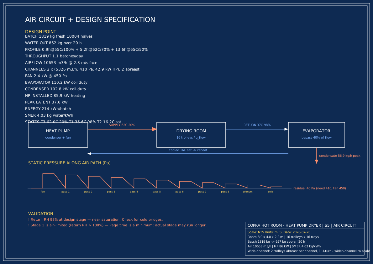
S5 — Air circuit schematic, pressure staircase along the air path, full spec table.
CFD simulation (qualitative)
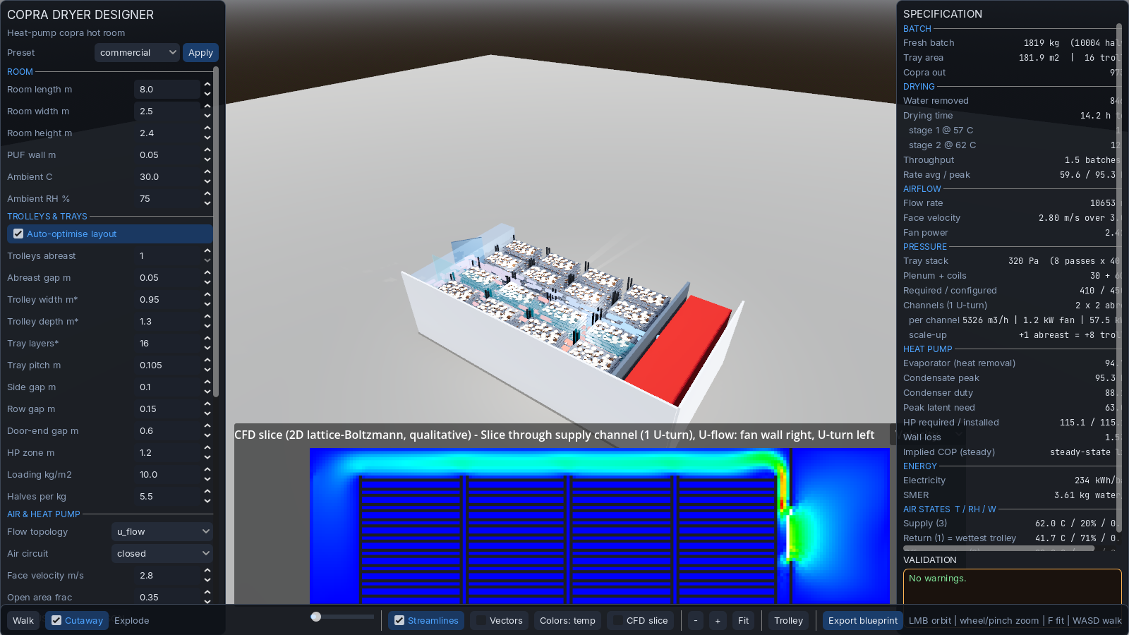
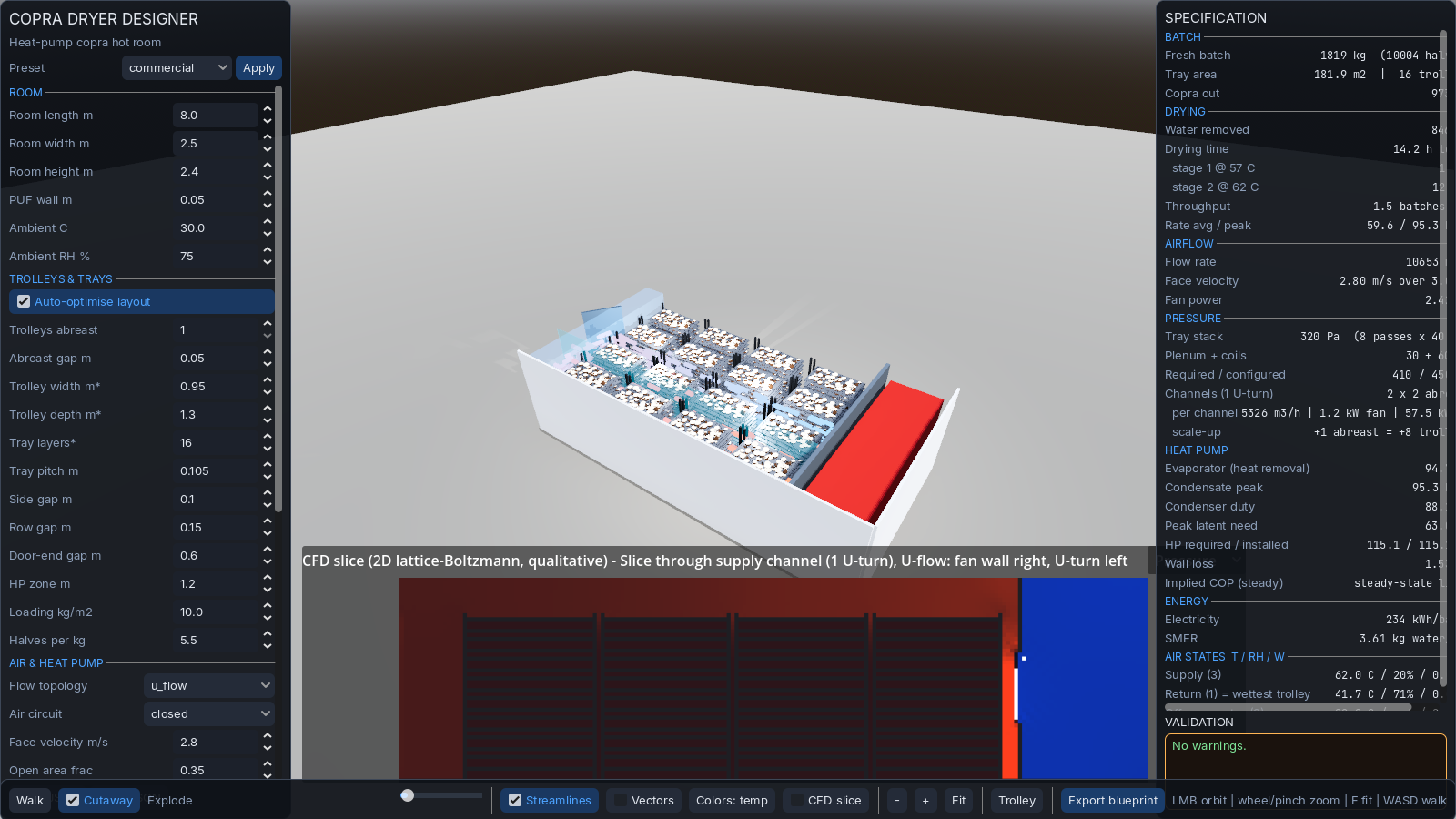
The 2D lattice-Boltzmann slice below shows the velocity field and relative pressure in a plane
through the supply channel. The fan-wall jet is clearly visible, the U-turn at the door end, and the
suction at the return. Dead zones are minimal.
Velocity magnitude — fan jet, channel flow, U-turn recirculation.Relative pressure — high (red) at supply, low (blue) at suction.
Fan schedule
Item
Spec
Qty
Recirculation fans
Centrifugal backward-curved, 5,400 m³/h @ 450 Pa each, 1.2 kW motor (IE3)
2 (one per channel)
Location
Fan wall at heat-pump partition, one supply + one return opening per channel
—
Drives
Direct-drive, VFD-controlled for multi-stage velocity trim