Controls, Electrical & Plumbing
Two-stage profile · sensor schedule · safety · utilities
Control logic
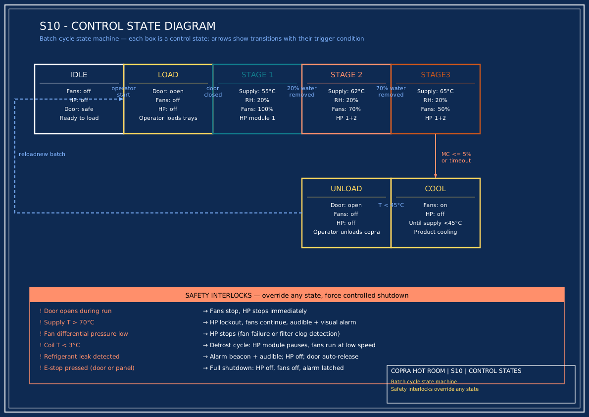
The batch cycle runs as a state machine (see S10 below for the full state diagram with transitions and safety interlocks). Each stage has explicit entry conditions and exit criteria, logged by the HMI for traceability.
- Load & start — operator confirms door closed, fans start at full speed, HP module 1 enabled.
- Stage 1 (surface drying) — supply setpoint 55°C, fans 100%. Duration 0.9 h OR until cumulative condensate reaches ~20% of expected water (172 L).
- Stage 2 (main drying) — supply ramps to 62°C at 0.5 K/min, fans drop to 70%. Module 2 enabled. Duration 5.2 h OR until 70% of water removed.
- Stage 3 (deep + finish) — supply ramps to 65°C, fans drop to 50%. Duration 13.6 h OR until product MC ≤ 6%.
- Cool-down & unload — fans run on at 30%, HP off, until supply < 45°C.
Sensor schedule
| Sensor | Range | Accuracy | Qty |
|---|---|---|---|
| Supply T + RH (post-condenser) | 0–80°C / 0–100% | ±0.3°C / ±2% | 1 |
| Return T + RH (off product) | 0–80°C / 0–100% | ±0.3°C / ±2% | 1 |
| Product core T (top tray, mid, bottom) | 0–100°C | ±0.5°C | 3 |
| Coil outlet T (evaporator) | -20 to +60°C | ±0.5°C | 1 |
| Differential pressure across fan | 0–1000 Pa | ±10 Pa | 1 |
| Condensate flow (turbine) | 0–50 L/h | ±1% | 1 |
| Door position switch | — | — | 1 |
| Refrigerant leak detector (in-room) | 0–1000 ppm | — | 1 |
Safety interlocks
- Door open → fans stop, HP stops (anti-hot-injury, anti-moisture-loss).
- Supply T > 70°C → HP locks out; fans continue; audible alarm.
- Low differential pressure (fan failure or filter clog) → HP stops.
- Coil T < 3°C → defrost cycle; HP module pauses, fans continue on low speed.
- Refrigerant leak → alarm beacon + audible; door auto-release; HP off.
- E-stop at door and at control panel.
Electrical
| Connected load | ~32 kW (HP 27 + fans 2.4 + aux 3) |
| Supply | 3-phase 415 V + neutral + earth, dedicated 100 A isolator |
| Power factor correction | To 0.95 at full load |
| HMI | 10" touch panel, batch logging (CSV), trend charts for T/RH/condensate |
Plumbing & drains
- Condensate — 32 mm SS to 200 L calibrated tank, daily drain to waste or recovery.
- Cleaning drain — 50 mm floor trap at the door end, capped during operation.
- Makeup air — optional motorised damper (5% of flow) for early-stage moisture purge; normally closed.
- Water supply — potable, for wash-down hosepoint at door.