Room Design & Layout
Insulated envelope · trolley grid · U-flow air path
Envelope specification
| Parameter | Value | Notes |
|---|---|---|
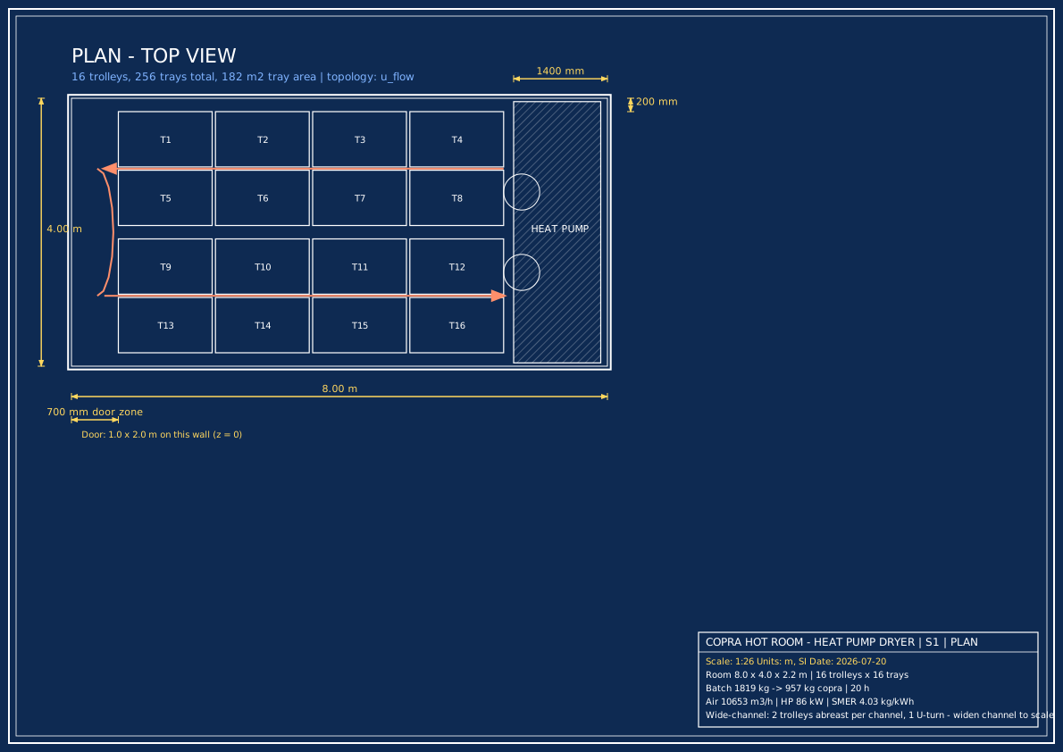
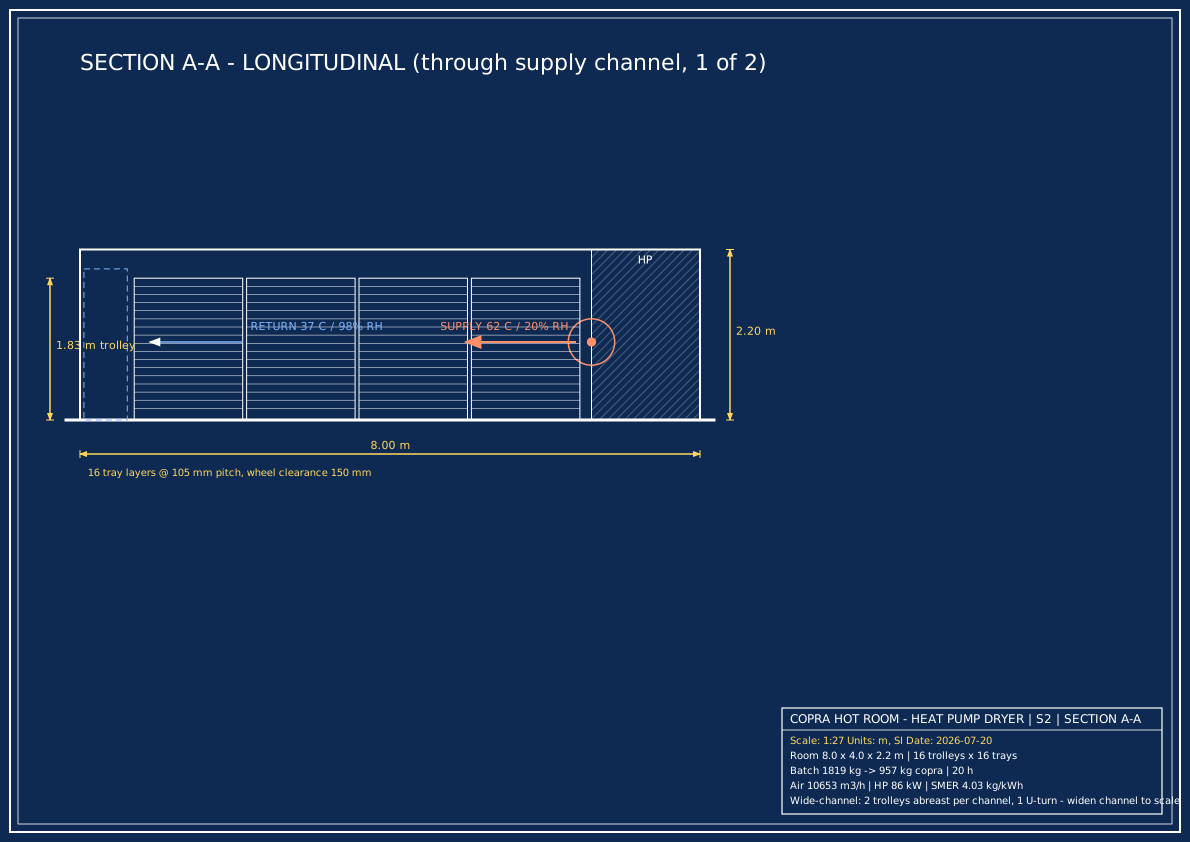
| Internal dimensions | 8.0 × 4.0 × 2.20 m (L × W × H) | Single bay; ~32.0 m² floor area |
| Wall / roof panels | 50 mm PUF sandwich, white food-grade steel facing | λ = 0.022 W/m·K → U ≈ 0.44 W/m²·K |
| Floor | 100 mm reinforced concrete, polyurethane-topped, coved to walls | Vapour barrier below slab; thermal break at panel base |
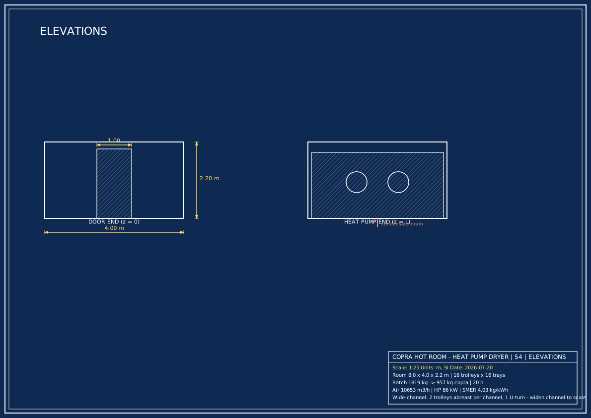
| Door | 1.0 × 2.0 m insulated, gasketed, outward-opening | Interlocked with fan & HP for safety |
| Vapour barrier | Continuous, sealed at all panel joints and floor junctions | Critical — moist 62°C air will condense on any cold bridge |
| Structure loss (design) | 1.7 kW | ΔT = 32 K vs 30°C ambient |
Trolley layout & air path
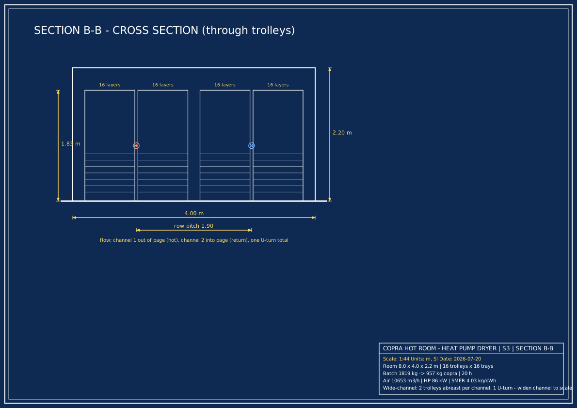
16 trolleys arranged in 2 channels of 2 abreast × 4 along the length. Air enters through a supply fan wall at the heat-pump end, travels through the supply channel (4 trolley passes in series), makes a single U-turn at the door end, and returns through the second channel (4 more passes) to the heat-pump intake. 8 total passes · 410 Pa pressure drop · identical air path for every trolley.
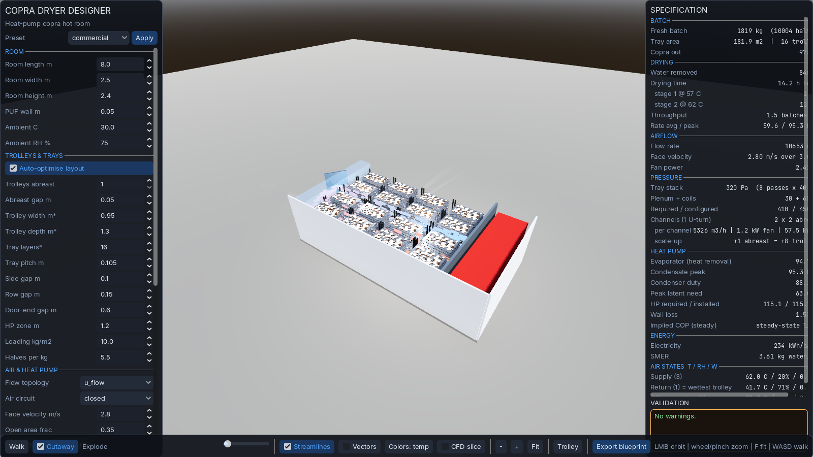
Cross-section and elevations