Heat-Pump Specification
Staged capacity · refrigerant · coils · compressor · condensate
Capacity & staging
| Required heating capacity (peak, with 15% margin) | 86 kW |
| Compressor electrical input (COP 3.2) | 27 kW · ~36 HP motor |
| Peak latent load | 37.6 kW |
| Average batch load | ~24 kW (HP will modulate) |
| Recommended arrangement | 2 × 50 kW modules in parallel (staged, redundant) |
| Alternative | 3 × 30 kW modules (finer staging, higher redundancy) |
Why staged modules, not one big unit
The batch moisture load peaks early and falls to ~50% by mid-cycle. A single 86 kW unit would short-cycle for the second half of the batch. Two 50 kW modules let you run both during the peak and drop to one as the load falls — better part-load efficiency and full redundancy (one module down = half capacity, not a stoppage). Standard 50 kW heat-pump units are easier to source than a custom 120 kW unit.
Refrigerant & coils
| Item | Specification |
|---|---|
| Refrigerant | R410A (acceptable) or R32 / R454B (low-GWP, recommended for new builds) |
| Evaporator coil | Fin-and-tube, 4-row, ~95 kW design duty, face area sized for <2.5 m/s face velocity |
| Condenser coil | Fin-and-tube, 4-row, ~88 kW design duty, reheat the mixed stream to 62°C |
| Condensate drain | 32 mm SS, U-trap (50 mm seal), routed to a 200 L holding tank for batch metering |
| Defrost | Hot-gas reverse-cycle; coil outlet ≥ 5°C at design point — defrost rare (governed by sensors) |
| Compressor | Scroll or screw, semi-hermetic, capacity control 25–100%, IE3 motor |
State diagram
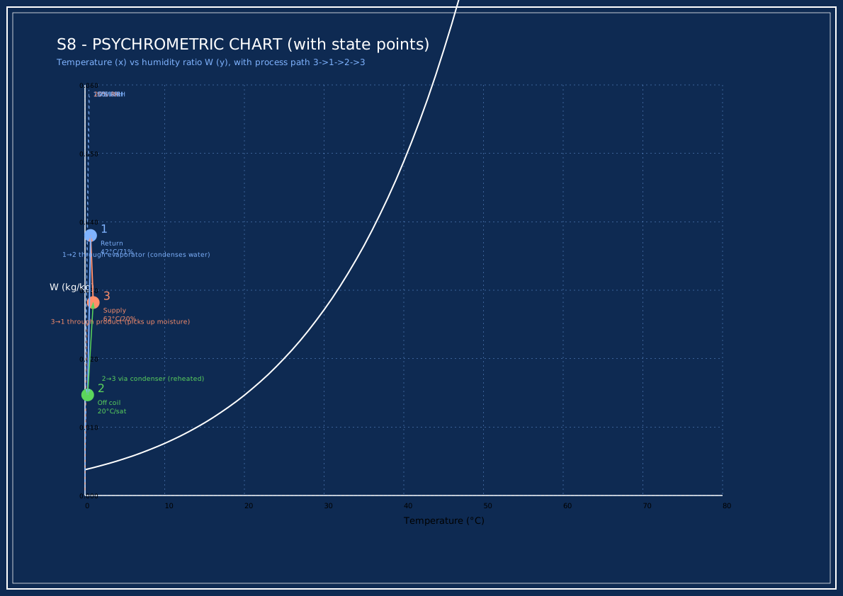
The psychrometric chart (S8) below shows the three air states on a temperature–humidity plot, with the process path: supply (3) → through product picking up moisture (1) → through evaporator condensing water (2) → reheated by condenser back to (3). The closed loop is clearly visible.
| Stage | State | T (°C) | RH (%) | W (kg/kg) |
|---|---|---|---|---|
| Supply (post-condenser) | 3 | 62.0 | 20 | 0.0282 |
| Return from product | 1 | 36.6 | 98 | 0.0380 |
| Off evaporator (sat) | 2 | 16.2 | 100 | — |
Vendor schedule (HP scope)
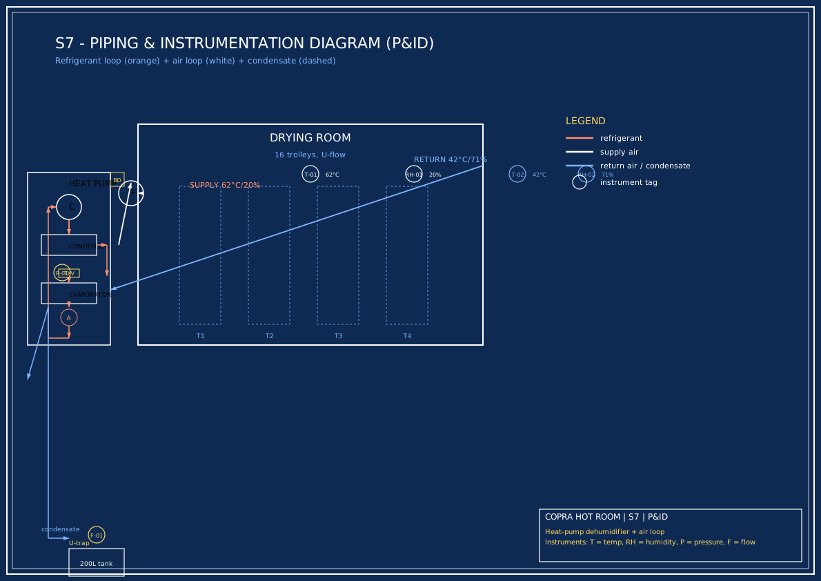
The P&ID below (S7) shows the complete piping, instrumentation, and air loop for one HP module plus the room. Vendors should confirm all instrument tags and pipe sizes against this diagram.
| Item | Qty | Spec |
|---|---|---|
| Heat-pump dehumidifier module | 2 | 50 kW heating, COP ≥ 3.2 at 62°C cond / 20°C evap, R410A or R32 |
| Evaporator condensate assembly | 2 | Per module, with U-trap and tank takeoff |
| Control panel per module | 2 | PLC with capacity control, Modbus RTU to master BMS |
| Refrigerant pressure / leak sensors | 2 sets | Hard interlock to fans and alarm beacon |
| Vibration isolators, refrigerant piping to module boundary | — | Per module |
Condensate management
~862 kg (litres) of water per batch is removed at the evaporator and drained as liquid. This is not vented — it is collected in a 200 L calibrated tank and measured each batch as a process check (sum of condensate + final moisture check = batch mass balance).